Ah - may be part of the reason it was on the market.
This can't be the case here as the B/Gr : B connector is open, yet there is 12V on the Black at the Alternator - must be a different wire.
This needs a flexible mental approach. Normally, you have a battery, switch, light, ground - the light always has 0V on the ground terminal and when you close the switch, the light has 12V on one side, 0V on the other - so it lights. Easy.
The alternator warning light is sort of the reverse. With the Ign switch ON, the light has 12V on one side and the (stationary) alternator looks like a direct connection to ground - so it lights.
Then the Alt starts to spin and the internal voltage rises. The light still has 12V on one side from the Ign. switch, but the Alt. no longer looks like a ground connection (0V), but rather a voltage source (14V). Now the light has 12V on one terminal and 14V on the other, so it sees only 2V which isn't enough to make it glow.
(this is more representative than literal as the Alt. output is connected the the battery, so the two voltages track each other much more closely than suggested)
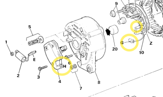
Found this pic on a random forum in a discussion on Ford tractors (model not specified)
View attachment 75400
Could you measure the resistance between these two terminals? (some diagrams show them as connected)
View attachment 75401
 ) binned dozens of perfectly good 17,s 19,s and 23,s when I cleared my yard