TEREX HD1000

H

Howdeedoodee

Member
Hi
It was a crap day raing all day here in Nottingham on Monday so I didn't get chance to take some more detailed short video clips and photo's.
I'm doing an extension digout tomorrow all day and it'll be a long 12 hour day.

So I'll do the video & photo's on Thursday.
I'll also do a few detailed sketches of the ignition switch indicating what connectors have 12volts at run & crank positions.

I did quickly have a look this evening in the dark with a torch to see where the start/stop solinoid was.
I found it so I unclipped the plug and gave all the pins a thorough clean and WD40.
The wires to it looked OK.
To add to the ignition sketch I'll also do sketches of things like alternator voltages, stop/start solenoid voltages, anti start module pins and whatever else i find when I'm at run and crank positions.

One thing that came to mind is that even though the ignition switch was perfectly clean inside I wonder if the copper tabs inside are worn and something isn't getting 12 volts.
Once I've done all the sketches with voltage details on I'm praying someone can point me as to whats wrong because I've god a dig out on Saturday that I've cancelled already and need the dumper for it.

Speak soon.
Thanks for all the help and pointers so far.
John
 
Mick-the-fitter

Mick-the-fitter

It’s what I do!
There are ways round most things, update me with photos and anything else you think of, I can guide you through a few short cuts.
 
H

Howdeedoodee

Member
Hi All

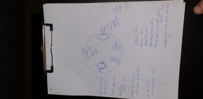
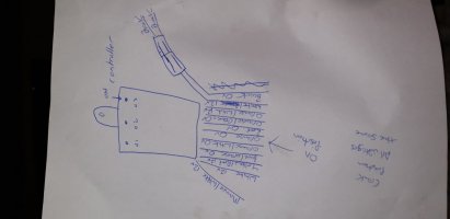
I've done some drawings of the following items listing wire colors and voltages at start and crank position.

1. Starter switch.
2. Anti- start module.
3. Alternator.
4. start stop solinoid.

I've also done a shorter slower video showing wiring etc.
Here's the video link
 

Attachments

  • 20211104_201144.jpg
    20211104_201144.jpg
    57.1 KB · Views: 680
  • 20211104_201227.jpg
    20211104_201227.jpg
    49.8 KB · Views: 555
  • 20211104_201326.jpg
    20211104_201326.jpg
    58.1 KB · Views: 725
Mick-the-fitter

Mick-the-fitter

It’s what I do!
Ok in the lever neutral position, ignition on, do you get fuel pump ticking and stop solenoid click? (ready to start) if you put a wire on the starter exciter wire does it turn over?
 
jd6820

jd6820

Well-known member
Hi All

I've done some drawings of the following items listing wire colors and voltages at start and crank position.

1. Starter switch.
2. Anti- start module.
3. Alternator.
4. start stop solinoid.

I've also done a shorter slower video showing wiring etc.
Here's the video link
Yeah, you should have power to the orange wire when the lever is in neutral. I bet if you applied power to the orange wire it will start. Then remove power to the orange so it thinks its in drive and the O3 light should extinguish and release park. At this point DO NOT try to drive it as I think when you are moving forward or reverse its signalling the box it is in neutral? That's what was confusing me earlier as to why the switch on the neutral for your joystick is working opposite to what I'm used to?
 
H

Howdeedoodee

Member
Ok in the lever neutral position, ignition on, do you get fuel pump ticking and stop solenoid click? (ready to start) if you put a wire on the starter exciter wire does it turn over?
No power on stop solinoid even with switch in on position.
If I put a wire on the exciter it starts and runs but stops if I take the wire off.
 
H

Howdeedoodee

Member
Yeah, you should have power to the orange wire when the lever is in neutral. I bet if you applied power to the orange wire it will start. Then remove power to the orange so it thinks its in drive and the O3 light should extinguish and release park. At this point DO NOT try to drive it as I think when you are moving forward or reverse its signalling the box it is in neutral? That's what was confusing me earlier as to why the switch on the neutral for your joystick is working opposite to what I'm used to?
Hi

When I put a jumper wire direct from the battery to the orange wire (at relay) it starts but stops as soon as I release the key from the spring loaded crank position.
It also stops if I remove the jumper wire to the orange wire.

When I run a live direct from battery to the starter motor exciter it starts and drives normally but stops as soon as I take that wire off.

Why when in start or run position is there no power to start stop solinoid?

I traced the red from start stop solinoid and it runs directly into the starter motor on a smaller white wire.
Im going to dismantle the starter to have a look.
 
H

Howdeedoodee

Member
Hi
I made another quite video with a question that i find odd.
Thanks in advance for any help you can give.
john

 
jd6820

jd6820

Well-known member
Hi
I made another quite video with a question that i find odd.
Thanks in advance for any help you can give.
john

Sounds like if it stops running the power supplied from the Orange/White wire on the anti-start module isn't getting to the hold coil on the stop solenoid or the hold coil is no good. Can you verify if the power from the orange/white is 12v getting to one of the three wires going to the run/stop solenoid on the back of the fuel injection pump? The wire you are tracing is correct but you don't want to keep using that to run it as you are keeping the starter engaged whilst engine is running and you'll burn out the pull coil too. A bad idea as @Mick-the-fitter pointed out earlier.
 
Mick-the-fitter

Mick-the-fitter

It’s what I do!
How many wires are going to the stop solenoid? 2 or 3
 
H

Howdeedoodee

Member

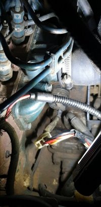
Attachments

  • Screenshot_20211107-201221_Video Player.jpg
    Screenshot_20211107-201221_Video Player.jpg
    120.6 KB · Views: 546
H

Howdeedoodee

Member
but only a 3 way connector ?
Hi
Yes.
3 pin connector.
1 pin with a thick black wire
1 pin with a thick red wire.
1 pin with 2 thinner wires which are white with orange stripes.
 
V8Druid

V8Druid

do it as well as you can,but learn to do it better
Hi
Yes.
3 pin connector.
1 pin with a thick black wire
1 pin with a thick red wire.
1 pin with 2 thinner wires which are white with orange stripes.
suggesting two sources of voltage ;)
 
H

Howdeedoodee

Member
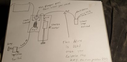
It doesn't make sense that the thick red wire on that 3 way connector is only ever live when the starter motor is initially cranked.
Then when you let go of the key for it return to run position that wire is dead??
 
Shovelhands

Shovelhands

Well-known member
It doesn't make sense that the thick red wire on that 3 way connector is only ever live when the starter motor is initially cranked.
Then when you let go of the key for it return to run position that wire is dead??
That wire is the powering the pulling coil at a guess. Holding coil should then take over.
 
V8Druid

V8Druid

do it as well as you can,but learn to do it better
It doesn't make sense that the thick red wire on that 3 way connector is only ever live when the starter motor is initially cranked.
Then when you let go of the key for it return to run position that wire is dead??
does the solenoid have a double throw for overfuel starts, like a cold start button on an old manual pump??
 
H

Howdeedoodee

Member
Like this drawing I did.
 

Attachments

  • 20211107_232207.jpg
    20211107_232207.jpg
    67.6 KB · Views: 498
Mick-the-fitter

Mick-the-fitter

It’s what I do!
Black earth, orange white holding current, red throwing current, red only puts a current into the solenoid for seconds, and when the ignition is on the orange and white current will hold the solenoid on, you can check these with a Volt meter, by putting a live 12vs to the red wire circuit you will damage the solenoid. But if you remove the solenoid and switch on the ignition, then flick the key to start position, the solenoid should throw in and stay in. If you remove the solenoid and start the engine it should run, you can stop it by pushing the end of the pump rack in, if the engine starts and runs, and the solenoid doesn’t work, then there lies the problem.
 
Top