Hi Folks..Not one for putting out for help due to overwhelming stubbornness I'm feeling a bit out of my comfort zone here and hoping for genuine help

G

Gary

Member
very nearly bought this, but got beaten to it by a local buyer close to the seller .... was a peach and looked a seriously nice tool ...
View attachment 19680View attachment 19681
sold for £2k .... a real peach
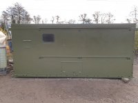
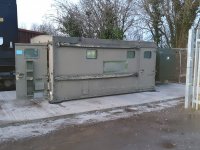
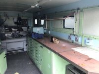
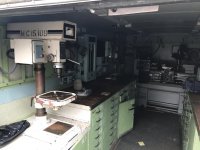
Just as a matter of any interest here's a pic of my thorn in my side in her final resting place..a bolted in the rain 🤨 not the workshop yet..waiting for another rainy day 🤣
 

Attachments

  • 20201123_132059.jpg
    20201123_132059.jpg
    184.3 KB · Views: 224
  • 20201125_163035.jpg
    20201125_163035.jpg
    231.2 KB · Views: 235
V8Druid

V8Druid

do it as well as you can,but learn to do it better
Geeeezzzz, only £2K..that makes me want to cry..I'd carry that home on my back if..well I feel a lot more hopeful I can have something up and running tidy by next Summer 🥳..
yeh I was gutted .. had had several conversations with the guy and had told him I'd like to come see it the next day, to buy it and he said he'd also been talking with someone local who was coming to see it that evening .... knew then, it'd sell :cry::cry: ..in fairness he rang me later in the evening to say it'd sold. Ajax cost me £2.7k
 
Lancs Lad

Lancs Lad

Well-known member
Just as a matter of any interest here's a pic of my thorn in my side in her final resting place..a bolted in the rain 🤨 not the workshop yet..waiting for another rainy day 🤣
Interested. That the demountable workshop? What sorta money?
 
G

Gary

Member
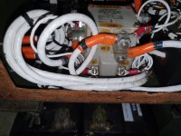
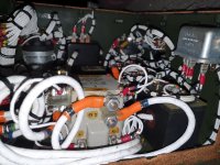
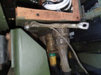
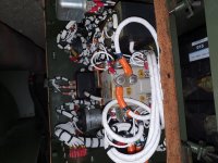
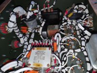
Here are a few more pics I've taken today..
 

Attachments

  • 20201128_122505.jpg
    20201128_122505.jpg
    165.4 KB · Views: 215
  • 20201128_122500.jpg
    20201128_122500.jpg
    197.2 KB · Views: 187
  • 20201128_122322.jpg
    20201128_122322.jpg
    152.3 KB · Views: 188
  • 20201128_122258.jpg
    20201128_122258.jpg
    192.6 KB · Views: 179
  • 20201127_151036.jpg
    20201127_151036.jpg
    253.6 KB · Views: 233
V8Druid

V8Druid

do it as well as you can,but learn to do it better
Unfortunately that's about as much space I had to get any better pic..I'll post what I have which may not be any use at all, the main leads are to the alternator,,yes using battery voltage and 24v system to the best of my memory 👴
forgot those extra pix the other night .... not a lot of room in there is there?!! :oops: weird set up that and belt driven :oops: ... not the most reliable of set ups
 
V8Druid

V8Druid

do it as well as you can,but learn to do it better
I know..it needs a lot of tlc but it will get it .👌
nice little M300 Harrison ... is that milling head movable along the bed length ? ..... I hope all those draws were full of goodies:unsure::giggle:
 
V8Druid

V8Druid

do it as well as you can,but learn to do it better
Here are a few more pics I've taken today..
well if that main relay's not making that's the reason there's nowt at yer output, I'd say .... if those are the alternator tails feeding into it
 
G

Gary

Member
well if that main relay's not making that's the reason there's nowt at yer output, I'd say .... if those are the alternator tails feeding into it
There's alternator leads and some but from where they're all coming from is not straight forward without
stripping looms and hardware..I've had 2 old skool genny engineers looking at it today and almost from script...piece of over complicated pain in the ass, they're contacting a ex Army mate Monday to see if he's any more knowledge..but my optimism and options are dwindling..next step Monday. 🤞
 
G

Gary

Member
nice little M300 Harrison ... is that milling head movable along the bed length ? ..... I hope all those draws were full of goodies:unsure::giggle:
Unfortunately that Mill attachment is static hense the looking in the future to purchase a little Bridgy or similar..yeah I wish those drawers were full of goodies but alas...bugger all 🙈 but I still have a good start of turning and milling cutters and most of my measuring kit I need so just need life into the old girl..😉
 
V8Druid

V8Druid

do it as well as you can,but learn to do it better
Unfortunately that Mill attachment is static hense the looking in the future to purchase a little Bridgy or similar..yeah I wish those drawers were full of goodies but alas...bugger all 🙈 but I still have a good start of turning and milling cutters and most of my measuring kit I need so just need life into the old girl..😉
you'll struggle to fit a turret in there anywhere .... My Ajax is as strategically placed as I can get it in the door way of one of my 40 footers and doesn't leave a great deal of room for getting in/out .. takes about 65% of the width of the doorway

WP_20190626_14_20_58_Pro.jpg
WP_20190626_18_16_35_Pro.jpg
WP_20190626_18_17_09_Pro.jpg
 
craig

craig

Well-known member
Just as a matter of any interest here's a pic of my thorn in my side in her final resting place..a bolted in the rain 🤨 not the workshop yet..waiting for another rainy day 🤣
Is your demountable workshop aluminium?
I moved one a few months back, and was quite surprised when I asked how heavy it was, as it couldn't get as close to it, as I would to liked, to lift it.
 
jd6820

jd6820

Well-known member
Wow! Lots of wires in that little box. Some have nowt to do with the generator I'd say? The Lucas regulator and relays are unlikely to be for the generator more likely the engine and its alternator for charging/starting purposes.

If you remove these the job starts to look more simple. The boxes to the right of the picture with large "shunt" resistor fixed to the top are Current transformers hence being marked 'CT'. The wires from the alternator that effectively become your phase supply lines (L1,L2,L3) are all passed through the middle of the coils to induce a voltage and drive the ammeters. The load energise relay is I suspect the way they allow the AVR to control the load output. If over excitation, over/under frequency or over/under voltage occur the AVR or its associated protection systems need to disconnect the load. As these systems aren't designed to control large loads the relay is used instead.

Does that load excite switch have the same numbers on the wires as x1 and x2 on the relay? It doesn't look like the AVR is situated in that box, if it is I can't see it...

The military stuff is way overkill and designed to run at full load or above and backup systems to protect against pretty much all faults. This over engineering makes diagnostics difficult. I have a 3 phase ex MOD genset that the AVR was knackered, well more specifically the protection circuit which were all rack mounted and spread across several PCB's with loads of old dried out electrolytic capacitors fitted and ageing solder joints I decided to rewire from scratch with a modern AVR and generator control unit. Whilst at the job I fitted modern MCB, RCCB's and voltage and current panel meters. It was a fairly involved job but well worth the effort. I think if you could find someone who understands the basic principles and follows the numbering system on the wires you might find a solution but it's a costly job if you cant do it yourself I'm afraid. Hence why the MOD low houred stuff makes little money compared with a main brand genset such as; Pramac, SDMO, Caterpillar etc...

Hopefully you can find someone to cast an eye over the load relay and it's control system as I believe that's where the fault lies. The AVR seems to be functioning correctly as the genset doesn't shut itself down when the load switch is toggled I assume?

 
V8Druid

V8Druid

do it as well as you can,but learn to do it better
Wow! Lots of wires in that little box. Some have nowt to do with the generator I'd say? The Lucas regulator and relays are unlikely to be for the generator more likely the engine and its alternator for charging/starting purposes.

If you remove these the job starts to look more simple. The boxes to the right of the picture with large "shunt" resistor fixed to the top are Current transformers hence being marked 'CT'. The wires from the alternator that effectively become your phase supply lines (L1,L2,L3) are all passed through the middle of the coils to induce a voltage and drive the ammeters. The load energise relay is I suspect the way they allow the AVR to control the load output. If over excitation, over/under frequency or over/under voltage occur the AVR or its associated protection systems need to disconnect the load. As these systems aren't designed to control large loads the relay is used instead.

Does that load excite switch have the same numbers on the wires as x1 and x2 on the relay? It doesn't look like the AVR is situated in that box, if it is I can't see it...

The military stuff is way overkill and designed to run at full load or above and backup systems to protect against pretty much all faults. This over engineering makes diagnostics difficult. I have a 3 phase ex MOD genset that the AVR was knackered, well more specifically the protection circuit which were all rack mounted and spread across several PCB's with loads of old dried out electrolytic capacitors fitted and ageing solder joints I decided to rewire from scratch with a modern AVR and generator control unit. Whilst at the job I fitted modern MCB, RCCB's and voltage and current panel meters. It was a fairly involved job but well worth the effort. I think if you could find someone who understands the basic principles and follows the numbering system on the wires you might find a solution but it's a costly job if you cant do it yourself I'm afraid. Hence why the MOD low houred stuff makes little money compared with a main brand genset such as; Pramac, SDMO, Caterpillar etc...

Hopefully you can find someone to cast an eye over the load relay and it's control system as I believe that's where the fault lies. The AVR seems to be functioning correctly as the genset doesn't shut itself down when the load switch is toggled I assume?
reckon VR1 in this is motor alternator @jd6820 ?? ..... could well explain why the main relay ain't latching and powering up the output sockets ??
1606602299951.png
 
jd6820

jd6820

Well-known member
reckon VR1 in this is motor alternator @jd6820 ?? ..... could well explain why the main relay ain't latching and powering up the output sockets ??
View attachment 19709
Yeah that's my guess, but not sure if engine alternator output would prevent Load relay energising. I suppose it could do though? My bets it has been disconnected when alternator replaced by a more modern unit with a built in regulator? All speculation without seeing it all.
 
V8Druid

V8Druid

do it as well as you can,but learn to do it better
Yeah that's my guess, but not sure if engine alternator output would prevent Load relay energising. I suppose it could do though? My bets it has been disconnected when alternator replaced by a more modern unit with a built in regulator? All speculation without seeing it all.
good call though ... could well be the case (y) ... 's been tidily done for sure :rolleyes:
 
G

Gary

Member
Is your demountable workshop aluminium?
I moved one a few months back, and was quite surprised when I asked how heavy it was, as it couldn't get as close to it, as I would to liked, to lift it.
Yes
 
Top