
Lincoln Welder - a little help needed

Gecko

Gecko

Well-known member
Once again, I've taken a chance and bought something interesting sight-unseen while out of the country (last time, it was a 3cx).
This time, it's an early 90's Lincoln diesel welder.
It was described as "no fuel at the pump", I took a punt and bought it.
A little more information - it's a 400A welder driven by a Perkins 4.236 (NA). Noting V8's mantra "clean the gauze in the unions"( (y) ) it seemed a fair bet.
I'm a little confused by the fuel lines though - it's gravity feed from the tank and it looks like the lift pump just circulates fuel from the tank to the filter with two lines off what is normally the bleed port (one from the injectors, the other?).
It'll probably be Jan before I get hands-on, but any pointers appreciated.

First question - any idea what model it is? The front panel has lost almost all it's information.
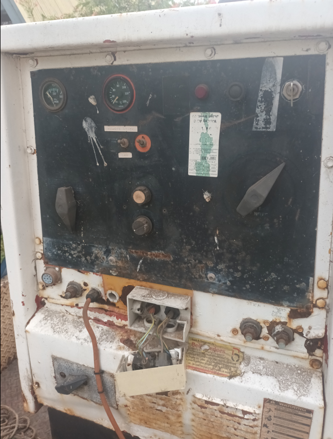
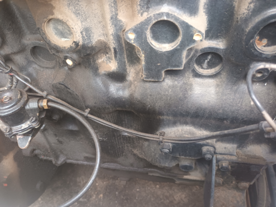
1699178727154.png


1699178817452.png


1699178889388.png
 
Mick-the-fitter

Mick-the-fitter

It’s what I do!
So far it looks fine to me, can’t see the pump in and out pipes, or the injection pump piping!
 
V8Druid

V8Druid

do it as well as you can,but learn to do it better
Once again, I've taken a chance and bought something interesting sight-unseen while out of the country (last time, it was a 3cx).
This time, it's an early 90's Lincoln diesel welder.
It was described as "no fuel at the pump", I took a punt and bought it.
A little more information - it's a 400A welder driven by a Perkins 4.236 (NA). Noting V8's mantra "clean the gauze in the unions"( (y) ) it seemed a fair bet.
I'm a little confused by the fuel lines though - it's gravity feed from the tank and it looks like the lift pump just circulates fuel from the tank to the filter with two lines off what is normally the bleed port (one from the injectors, the other?).
It'll probably be Jan before I get hands-on, but any pointers appreciated.

First question - any idea what model it is? The front panel has lost almost all it's information.
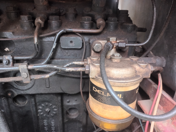
View attachment 52944

View attachment 52945

View attachment 52946
the other will almost certainly feed the 'flame thrower' cold start glow plug in the inlet manifold on a 4 pot Perky

this may well be the latest version

closer ........

1699207853188.png
1699207961870.png

1699208064426.png
closer .......
1699209927857.png
1699209868375.png
 
Gecko

Gecko

Well-known member
the other will almost certainly feed the 'flame thrower' cold start glow plug in the inlet manifold on a 4 pot Perky
Ah - yes, of course.
I've been downloading manuals from Lincoln, but nothing is close (enough) so far.

So far it looks fine to me, can’t see the pump in and out pipes, or the injection pump piping!
It all looks pretty tidy TBH
1699242766809.png

1699243123079.png
 
Last edited:
Gecko

Gecko

Well-known member
In a previous life, I worked in a motorbike workshop. The full time mechanic was very good, but he didn't have the problem solving skills when things got weird - I got those jobs. Anyway, one thing I learnt quickly was to innocently ask the owner what they'd done to try to fix the problem (so I knew what "else" was wrong - obviously it hadn't helped, or they wouldn't have brought the bike in.) It's exactly what makes this joke both funny and painful at the same time.
1699256600076.png


So - back to the point - any guesses where this red wire goes/does?

1699255375441.png

[for those less familiar with startermotors, the terminal the wire is connected to carries the heavy start current, but only when the key is turned. The rest of the time, it is unpowered]
 
Last edited:
V8Druid

V8Druid

do it as well as you can,but learn to do it better
In a previous life, I worked in a motorbike workshop. The full time mechanic was very good, but he didn't have the problem solving skills when things got weird. Anyway, one thing I learnt quickly was to innocently ask the owner what they'd done to try to fix the problem (so I knew what "else" was wrong - obviously it hadn't helped, or they wouldn't have brought the bike in.) It's exactly what makes this joke both funny and painful at the same time.
View attachment 53003

So - back to the point - any guesses where this red wire goes/does?

View attachment 53001
[for those less familiar with startermotors, the terminal the wire is connected to carries the heavy start current, but only when the key is turned. The rest of the time, it is unpowered]
probably/possibly the ign key in crank position ... usually when you go from ign on to crank it cuts the feed to/from the switch to anything else ... would also maintain the feed to the flame thrower in the inlet ... can't see why else you'd have a feed from a pole that is only energised in crank position
 
Gecko

Gecko

Well-known member
probably/possibly the ign key in crank position ... usually when you go from ign on to crank it cuts the feed to/from the switch to anything else ... would also maintain the feed to the flame thrower in the inlet ... can't see why else you'd have a feed from a pole that is only energised in crank position
Good idea, but no.
 
V8Druid

V8Druid

do it as well as you can,but learn to do it better
Low oil pressure cutout switch bypass?
quite poss .... SD1 oil pressure switches had three terminals, one which bypassed the low oil pressure cut out to ign module for cranking ... or you'd crank forever until / if the oil pressure ever built high enough to actually energise the ign. module to produce sparks .... as long as you hadn't flooded it by that time :rolleyes:
interestingly SD1 pressure was only 28psi at 2000 rpm, so cranking produced very little pressure.
 
Gecko

Gecko

Well-known member
Time to 'fess up
1699291031925.png


The hint was what I'd learnt working on other peoples bikes - find what the last guy did, and put back the way it should be.
The RED wire here is the output from the alternator (FFS). A trivial job it fix, but what were they thinking?
 
Gecko

Gecko

Well-known member
Ok, I've finally got my hands on this beast and seen it for the first time - wow, it's rough!
The engine looks pristine - except it doesn't run :(.
The housing on the other hand looks like it fell off the back of a truck several times (it's not pretty).

The story is the previous owner bought in "not running", tried to get it going - failed, ignored it a couple of years and sold it (to me).
So far, I've moved the alternator output to the solenoid terminal, so it can actually do something useful.
Then I started at the lift pump - cleaned the debris from inside, but noted nothing on the screen.
Replaced the '296 filter (the old one looked virgin inside), bled it from the lift pump, filter, thermostart and the injector pump (input screen, two bleeds and the return) - all seemed fine, but no flow on the injector lines while cranking.

Starting to wonder if the fuel cutout can stick inside the pump?
One thing is that someone in it's history seems to have had an O-ring fetish, so many of the olive seals have had O-rings added in-front of the olive. When I tried to put the lines back together without the o-rings, I found that the flare-nuts bottom before compressing the olive.

In this pic, I assumed the "Bolt" to be "banjo bolt"
1707029002654.png


... apparently not
1707029059467.png

I'm trying to decide if this is intentional or not - the thread (inside the banjo) would allow the injectors to drain back to the tank, but why use a banjo fitting rather than straight back to the tank? Anyone seen this setup?
 
Last edited:
Mogman

Mogman

What man as done, man can do, what never has,maybe
Ok, I've finally got my hands on this beast and seen it for the first time - wow, it's rough!
The engine looks pristine - except it doesn't run :(.
The housing on the other hand looks like it fell off the back of a stuck several times (it's not pretty).

The story is the previous owner bought in "not running", tried to get it going - failed, ignored it a couple of years and sold it (to me).
So far, I've moved the alternator output to the solenoid terminal, so it can actually do something useful.
Then I started at the lift pump - cleans the debris from inside, but noted nothing on the screen.
Replaced the '296 filter (the old one looked virgin inside), bled it from the lift pump, filter, thermostart and the injector pump (input screen, two bleeds and the return) - all seemed fine, but no flow on the injector lines while cranking.

Starting to wonder if the fuel cutout can stick inside the pump?
One thing is that someone in it's history seems to have had an O-ring fetish, so many of the olive seals have had O-rings added in-front of the olive. When I tried to put the lines back together without the o-rings, I found that the flare-nuts bottom before compressing the olive.

In this pic, I assumed the "Bolt" to be "banjo bolt"
View attachment 57312


... apparently not
View attachment 57314
I'm trying to decide if this is intentional or not - the thread (inside the banjo) would allow the injectors to drain back to the tank, but why use a banjo fitting rather than straight back to the tank? Anyone seen this setup?
That should be a banjo bolt👆
 
V8Druid

V8Druid

do it as well as you can,but learn to do it better
That should be a banjo bolt👆
only if there is a hole in the bottom of the spigot it screws into ... there will be enough room around the bolt for the fuel to return to tank in the body of the banjo fitting IMHDO
 
V8Druid

V8Druid

do it as well as you can,but learn to do it better
Yes but it also vents the air from the top of the filter head back to tank
if there is a hole in the spigot into the body of the filter ? and should be no air in the top of filter housing
 
Top