
Pel-Job TB 650 S: Track came loose

Kjeles

Kjeles

New member
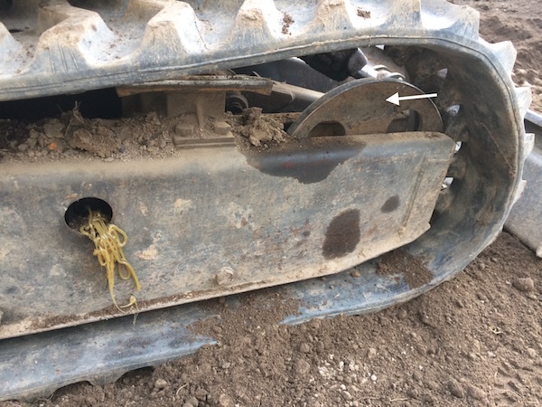
Hi folks, can anyone give me some advice? I got a stone stuck in the track today on a Pel-Job TB 650 S mini excavator. After moving back and forth a bit to get it loose, I heard a thunk sound. Shortly after, grease had squirted out from the grease point (see photo), the front wheel had moved towards the back (arrow on photo) and the track was loose.
Any idea what has happened?
Is there a tensioner behind the cover that has broken?
Any hints as to how to attack the problem?
BeltOff.jpg
 
Left hooker

Left hooker

Well-known member
The valve has either undone some how or has been snapped off by looks of it and with the story of a big rock would say the latter
 
Shovelhands

Shovelhands

Well-known member
If the grease has come out of that point then it’s just blown the valve out.
 
Kjeles

Kjeles

New member
Thanks.
Sorry for being so ignorant: Does this mean that the wheel is held in place by grease pressure?
Can I get to the grease valve by removing the outer, heavy steel body? It seems to be part of the frame and impossible remove.

Track.jpeg
 
Last edited:
Shovelhands

Shovelhands

Well-known member
Thanks.
Sorry for being so ignorant: Does this mean that the wheel is held in place by grease pressure?
Yes.
there’s a hydraulic cylinder of sorts, but filled with grease. You pump grease in to tension the tracks, through an ordinary grease nipple.
it looks to me like the grease has been ejected out of said nipple! (there’s some serious jokes and innuendo here, but I will resist 🤪)....Anyway, the grease nipple is not what holds the pressure, even though a grease nipple has a sprung loaded ball valve built in. The nipple is usually screwed into a one way valve, it’s this valve that actually holds the pressure.
from the stream of grease that’s on the frame it certainly looks like it’s come out of the nipple, therefore the valve behind it must be broken or jammed?
have a look at the other side first, so you can see what your dealing with. But essentially you’ve got to clean that grease off and investigate it further. Usually there’s a large hex that the grease nipple is screwed in to, slackening this usually releases the tension on the track.
it might be a simple fix and there’s no valve, only relying on the ball valve in the grease nipple, but I’ve never come across one like that, however, I’m not familiar with the model of machine you have, so don’t take my word for it.
 
M

Monkeybusiness

Well-known member
Further to Shovelhands post above - the grease nipple tensioner valve is attached to the wheel (white arrow in your pic) as a complete assembly. With the track removed the whole lot will slide forwards out of the main frame. None of that assembly is shown in your schematic.
 
Shovelhands

Shovelhands

Well-known member
Further to Shovelhands post above - the grease nipple tensioner valve is attached to the wheel (white arrow in your pic) as a complete assembly. With the track removed the whole lot will slide forwards out of the main frame. None of that assembly is shown in your schematic.
I didn’t even see the diagram 🤦‍♂️
 
Shovelhands

Shovelhands

Well-known member
As @Monkeybusiness says, the tensioner and idler assembly is not shown in that diagram and it should pull out of the end of the frame in one assembly. However, I’d expect the valve to be removable through the hole in the side of the track frame, if it’s not then I’d think it was a pretty shite design imo!
 
Kjeles

Kjeles

New member
Thanks again!
Here's a diagram of the innards. Does all this slide forward and out as a unit after removing some bolts?

Wheel.jpeg
 
Last edited:
Shovelhands

Shovelhands

Well-known member
I can’t quite read the numbers properly on my phone, but I think 36 is the grease nipple and 28 is the valve. The valve should unscrew and come out through the hole in the frame in my opinion
 
V8Druid

V8Druid

do it as well as you can,but learn to do it better
21 is the cylinder and 22 is the rod/piston .... 30/31/32 looks to be the seal pack, which're presumably ok as it's ejected its grease through the fill point 36/ 28? or 38? (can't read it) which is the one way valve mentioned above

the grease pressure in 21's assembly preloads the spring 25? which compensates/allows for a bit of movement in the track length, whilst kept tensioned as it traverses uneven ground and allows the track to 'soak up' / bend over, obstacles
 
Kjeles

Kjeles

New member
Thanks guys for guiding me through this problem! I was afraid my dear little digger was destined for the scrap yard.

It turned out that the tip of the grease nipple had been scratched such that the steel ball had popped out. Alternatively, the steel ball had popped due to high pressure when the rock got stuck in the belt.

The base of the nipple, part 28 on the diagram above, did not contain any valve, maybe because it is such a small excavator. The only thing holding the grease in place appears, therefore, to be the nipple ball.

I got a new nipple for $1, and the machine was good to go. Happy ending! :)

IMG_2312.JPG
 
Kjeles

Kjeles

New member
Correction to my posting above: The excavator has valves originally. I found them in the tool box. A former owner has apparently removed them.
That might be the reason the nipple ball popped.
 
Last edited:
Shovelhands

Shovelhands

Well-known member
Correction to my posting above: The excavator has valves originally. I found them in the tool box. A former owner has apparently removed them.
That might be the reason the nipple ball popped.
I’d say so. Be very unusual to just rely on the grease nipple alone.
 
Mick-the-fitter

Mick-the-fitter

It’s what I do!
To much pressure for a grease nipple, but I would do it to get out of trouble and put it on the lorry!
 
Top