Barford SX7000

S

SpringM

New member
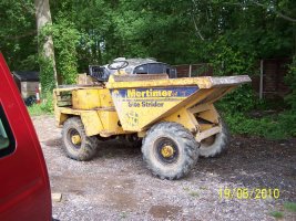
I am looking for a wiring diagram for a Barford SX7000 manufactured 2006.
I am using the diagram found on this forum for the Thwaites 6Ton machine which seems to have a lot of similarities to the wiring on the machine but the actual diagram would make things simpler .
Can anyone point me in the right direction.

Thanks
 
Mick-the-fitter

Mick-the-fitter

It’s what I do!
What are you looking for in the wiring?
 
V8Druid

V8Druid

do it as well as you can,but learn to do it better
I am looking to check out the starter circuit. Machine will crank when jumped from battery to starter motor but will not crank using key.
do you have a live at the ign switch and is it exiting the switch at the crank position ? do you have a live at the starter's solenoid connection .... if the answer to those is yes, then suspect the solenoid ... have you tried energising the solenoid with a jumper to it's spade connection to rule it out ?
 
jd6820

jd6820

Well-known member
Earth between battery and chassis is common for corroding on these then engine doesn’t get a good enough ground for the starter. The start circuit also goes through the brake pedal and neutral on the shuttle if it’s the same as every other barford I’ve worked on. Why they put the relays and fuses on the backside of the panel in front of your knees when driving is beyond me as water runs down the panel into the holders and corrodes stuff for fun! 🤦‍♂️
 
V8Druid

V8Druid

do it as well as you can,but learn to do it better
Earth between battery and chassis is common for corroding on these then engine doesn’t get a good enough ground for the starter. The start circuit also goes through the brake pedal and neutral on the shuttle if it’s the same as every other barford I’ve worked on. Why they put the relays and fuses on the backside of the panel in front of your knees when driving is beyond me as water runs down the panel into the holders and corrodes stuff for fun! 🤦‍♂️
forgot about the neutral position on the shuttle switch ... my Thwaites Alldrive is particularly finnicky about being in the exact position (y)
 
V8Druid

V8Druid

do it as well as you can,but learn to do it better
Starter Relay?😊
starter's working from a direct jump, hence check solenoid is too, to make sure the unit's functional ...
then work back or forwards looking for voltage, for a start, whilst checking for lectrickery from / to ign sw. end too .... follow the bread crumbs ;):)
 
Mick-the-fitter

Mick-the-fitter

It’s what I do!
starter's working from a direct jump, hence check solenoid is too, to make sure the unit's functional ...
then work back or forwards looking for voltage, for a start, whilst checking for lectrickery from / to ign sw. end too .... follow the bread crumbs ;):)
As long as the birds haven’t eaten them!😊
 
S

SpringM

New member
do you have a live at the ign switch and is it exiting the switch at the crank position ? do you have a live at the starter's solenoid connection .... if the answer to those is yes, then suspect the solenoid ... have you tried energising the solenoid with a jumper to it's spade connection to rule it out ?
Hi All, Thanks for input which was spot on.
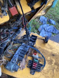
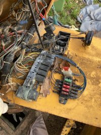
Starting problem now resolved two badly corroded cables 5 loose terminal connections and totally corroded starter relay which came in pieces when pulling terminals from base. Dumper starts but will not drive perhaps due to standing for 3 months but that is another issue for another day.
Wiring diagram would still be useful to identify the purpose of the 6 similar sized relays the larger on the end and the single relay mounted in a group of 4 receivers with base on cabling harness.
For info this dumper belongs to my son in law and daughter and is being used for their self build. This is their third machine and it seems to have fallen to me to help keep them operating and I am very much learning as I go along.
 

Attachments

  • IMG_0147.JPEG
    IMG_0147.JPEG
    285.6 KB · Views: 530
  • IMG_0146.JPEG
    IMG_0146.JPEG
    296 KB · Views: 677
  • IMG_7920.JPEG
    IMG_7920.JPEG
    205.7 KB · Views: 276
  • Mortimer dumper June 10 001.jpg
    Mortimer dumper June 10 001.jpg
    345.6 KB · Views: 410
  • Field 30 April 06 005.jpg
    Field 30 April 06 005.jpg
    392.4 KB · Views: 270
Last edited:
V8Druid

V8Druid

do it as well as you can,but learn to do it better
Hi All, Thanks for input which was spot on.
.......... Dumper starts but will not drive perhaps due to standing for 3 months but that is another issue for another day.
Wiring diagram would still be useful to identify the purpose of the 6 similar sized relays the larger on the end and the single relay mounted in a group of 4 receivers with base on cabling harness.
For info this dumper belongs to my son in law and daughter and is being used for their self build. This is their third machine and it seems to have fallen to me to help keep them operating and I am very much learning as I go along.
my prime suspect would be the direction control switch for the shuttle ...
 
Mick-the-fitter

Mick-the-fitter

It’s what I do!
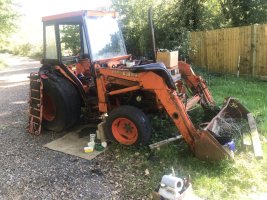
What is the green bit of kit? Bison may be
 
S

SpringM

New member
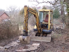
Sorry I was never able to identify that machine. It was pretty soon moved on for an electric start Mortimer Strider when they got tired of swinging the starting crank.:)
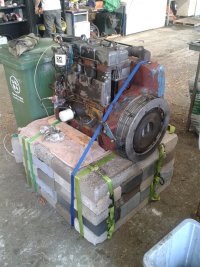
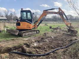
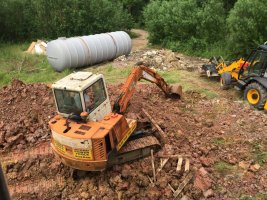
They are also on their third digger first a Komatsu then a Daewoo DH50 now a Hanex H55 also a pic of the ST3 from the site stridder which I completely rebuilt and bench tested in 2010. Also have a Kubota tractor tostop me getting boredo_O
:)
 

Attachments

  • 2014-08-10 15.50.19.jpg
    2014-08-10 15.50.19.jpg
    249.6 KB · Views: 253
  • IMG_4534.JPEG
    IMG_4534.JPEG
    348.3 KB · Views: 230
  • IMG_1437.JPG
    IMG_1437.JPG
    391.4 KB · Views: 212
  • Field 12 Mar 06 006.jpg
    Field 12 Mar 06 006.jpg
    335.4 KB · Views: 218
  • IMG_3264.JPEG
    IMG_3264.JPEG
    313.5 KB · Views: 271
S

SpringM

New member
Update re not driving.
After spending time in yesterdays sunshine following cables and checking for voltage noticed that voltage at some locations was only 8.5V compared with battery voltage of 12.5V this seemed to be due to poor contact of multi meter probe since scratching improved matters.
When checking shuttle lever terminals they sometimes showed 12.5V for a moment before settling back to around 8.5V so went back to fuses on panel as seen in earlier image 0146 and checking across fuse carrier terminals showed all to be output of 8.5V with 12.5V input. Removed fuses and checked each for continuity to discover they were all showing around 10k ohms resistance despite cleaning blades.
Changed all fuses and everything worked including reversing beeper which had not previously been working.
Thanks for everyone's input which was very helpful in confirming we were on the right track.
A question regarding the button on the gear change lever. I imagine this must somehow interrupt the drive momentarily to allow gear changes but I cannot see how the output cables from the button switch interface with shuttle drive system. Is anyone able to clarify please.
 
Top