R

You are using an out of date browser. It may not display this or other websites correctly.
You should upgrade or use an alternative browser.
You should upgrade or use an alternative browser.


Gecko
Well-known member
It'd be pretty old-school if it were a magnet coil. Only two wires though - you are in with a chance. (could be earth return I guess)
Start with a multimeter across the two wires. set the meter to low-ohms and take a reading. Then reverse the connections and see if you get the same reading.
Then check each wire to the case of the sensor.
Edit:
You can check the other end too. Stuff the multimeter probes into the mating connector and see if a voltage is present (either across the two wires or to ground).
Some good procedures here too

 axleaddict.com
Start with a multimeter across the two wires. set the meter to low-ohms and take a reading. Then reverse the connections and see if you get the same reading.
Then check each wire to the case of the sensor.
Edit:
You can check the other end too. Stuff the multimeter probes into the mating connector and see if a voltage is present (either across the two wires or to ground).
Some good procedures here too
DIY Auto Service: Permanent Magnet and Hall Effect Sensor Diagnosis and Testing
VSS, WSS, CKT and CMP speed and position sensors are used by the ECM or other computers to keep track of the position and speed of the crankshaft and camshaft, and the speed of the vehicle and its wheels.
axleaddict.com
Last edited:

V8Druid
do it as well as you can,but learn to do it better
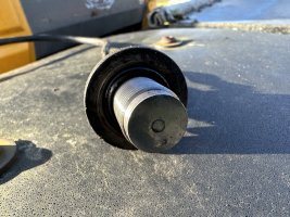
would imagine it's a Hall effect sensor and needs a pulse / regular exciter ...... usually a very small air gap between the tip and the energiser 'tab' ... might want adjusting closer to it's energiser/signal provider ... it should have a resistance if OK ... copper coil wound round a rod magnet ... as the exciter passes the tip it generates an electrical pulse, much like an ABS sensor on a vehicle's wheel hub or a Hall effect electronic dizzy in a petrol engineHi All, Does anyone know if there is a test that can be carried out in a speed sensor? I believe it’s a magnetic sensor but not 100%.
Voltmeter and a magnetic? Would it work?
It’s from a JCB Fastrac 145
View attachment 43020
R
rossandson
Well-known member
I'm wondering it it should have a little nipple on the end that possible has broken off? Unsure, struggling to find pictures or diagrams of replacements.
V8Druid
do it as well as you can,but learn to do it better
very unlikely ... usually flat faced .... the air gap between the sensor and rotor exciter is VERY small (couple of thou), but DO NOT use metallic feeler gauges to set it ... piece of very thin card, like a fag packet .... circa 8-10 thou. max. ... or .... back off the lock nut, lightly pinch the sensor down onto its exciter, then back it off slightly, sufficient to give a fine clearance, then lock it in position with the lock nut .... what rotary shaft is that sensor located adjacent to?I'm wondering it it should have a little nipple on the end that possible has broken off? Unsure, struggling to find pictures or diagrams of replacements.
R
rossandson
Well-known member
The installation instructions in the manual, wind it in until it stops then back it off , quarter turn from memory, need to check. Need to get it back out (put it back in to stop anything dropping in the hole.) Check with multimeter see what it reads, just don't want to go spending money on parts and it isn't the issue. As speed sensor is not the cheapest!very unlikely ... usually flat faced .... the air gap between the sensor and rotor exciter is VERY small (couple of thou), but DO NOT use metallic feeler gauges to set it ... piece of very thin card, like a fag packet .... circa 8-10 thou. max. ... or .... back off the lock nut, lightly pinch the sensor down onto its exciter, then back it off slightly, sufficient to give a fine clearance, then lock it in position with the lock nut .... what rotary shaft is that sensor located adjacent to?

V8Druid
do it as well as you can,but learn to do it better
where is "the hole" .... axle case/diff case/hub/?/prop. ...The installation instructions in the manual, wind it in until it stops then back it off , quarter turn from memory, need to check. Need to get it back out (put it back in to stop anything dropping in the hole.) Check with multimeter see what it reads, just don't want to go spending money on parts and it isn't the issue. As speed sensor is not the cheapest!
would guess from your " installation instructions in the manual, " that the pulse is provided by a hole/slot in the rotary face, rather than a raised tab, or you would need to align any tab to set the height/air gap.
Last edited:
R
rossandson
Well-known member
I'll be honest im probably slightly out my depth as usual but we shall carry on! ha!where is "the hole" .... axle case/diff case/hub/?/prop. ...
would guess from your " installation instructions in the manual, " that the pulse is provided by a hole/slot in the rotary face, rather than a raised tab, or you would need to align any tab.
Top of gear box under cab at back.
V8Druid
do it as well as you can,but learn to do it better
best guess'd be final motion/output shaft, in order for it to be accurate in all gears/speeds ... guessed it was oil immersed, by the oil in the threads of your first pic. ... have you tried to reset the gap? a quarter turn, back off, sounds realisticI'll be honest im probably slightly out my depth as usual but we shall carry on! ha!
Top of gear box under cab at back.
View attachment 43023
like Gecko says, I'd be testing for continuity and voltage from the socket it connects to .... may just be a broken wire somewhere and a new unit'd be an expensive way of finding the sensor is not at fault
V8Druid
do it as well as you can,but learn to do it better
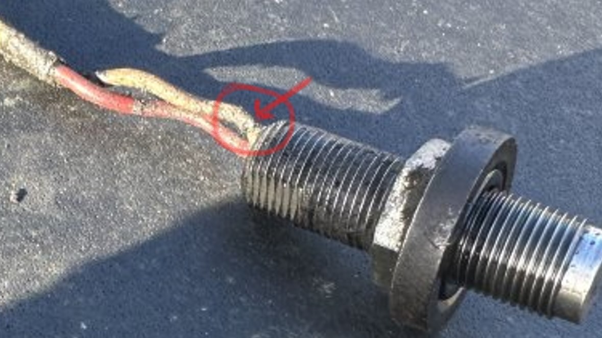
is this a damaged wire or just the pic?
R
rossandson
Well-known member
Yes that one wire has a bit of bare wire on. However have to hold my hands up. Unsure if it was damaged before if I did it getting it out but I think it was damaged already but caked in dirt.is this a damaged wire or just the pic?
View attachment 43024
However it was loose, I cleaned the area up best I could (no room to work at all and I’m thin!) then went to get spanner, squeezed back into a position to get to it and put spanner on it and it had no resistance at all I then undid all by hand. So I do wonder it it was loose to start with.
But the wire being unsleeved as such in one place, I thought about just taping it up or heatshrink best I could OR does this affect the performance?


pettsy
Well-known member
Might be worth asking on https://thefarmingforum.co.uk/index.php?forums/-/list

Mick-the-fitter
It’s what I do!
Does it have an LED on the back by the two cables? Put an ohm meter across the plug and pass a magnet over the end!
V8Druid
do it as well as you can,but learn to do it better
the signal generated is so small, just about anything could piss it off .... as for being loose ..... the air gap as said is miniscule ... a half a turn could be the difference between functionality ... or not behaving as it should. certainly repair the wire's outer sheath as best you can to insulate it to avoid any chance of the signal earthing out. It is also possibly quite critical that the wire is of a specific resistance ... any strand breakage will increase the resistance levelYes that one wire has a bit of bare wire on. However have to hold my hands up. Unsure if it was damaged before if I did it getting it out but I think it was damaged already but caked in dirt.
However it was loose, I cleaned the area up best I could (no room to work at all and I’m thin!) then went to get spanner, squeezed back into a position to get to it and put spanner on it and it had no resistance at all I then undid all by hand. So I do wonder it it was loose to start with.
But the wire being unsleeved as such in one place, I thought about just taping it up or heatshrink best I could OR does this affect the performance?

jd6820
Well-known member
Easy way to check those sensors is with a wide wood drill of the spade variety. As one of the tips or wings passes the end of the sensor is close proximity then followed by a gap it pulses. You'll need a multimeter that can measure hertz (HZ), hold the sensor in a vice (gently) and hold the drill bit wide side as close as you dare to the sensor. Spin drill up at various speeds and as long as you don't move more than a couple of mm away it should read fairly consistent at a certain RPM, vary the rpm to check it works at numerous speeds. The 145 has a gear on the range shaft to measure speed which is then linked up to the little module on the dash board. Which I think is an RDS unit re-branded?
The sensor looks fine in the picture, no issues there. It doesn't have an LED as it isnt of the reed switch variety, it's a hall effect sensor for counting pulses.
As the book describes, screw sensor in till it makes light contact with the tone wheel then backout slightly (1/4-1/2 turn won't matter which), common sensor on a lot of tractors. MF in particular.
Also wire repair, as long as the strands aren't severed, just cover up with heatshrink, tape or glue and carry on. They aint too fussed as long as the copper is still good.
The sensor looks fine in the picture, no issues there. It doesn't have an LED as it isnt of the reed switch variety, it's a hall effect sensor for counting pulses.
As the book describes, screw sensor in till it makes light contact with the tone wheel then backout slightly (1/4-1/2 turn won't matter which), common sensor on a lot of tractors. MF in particular.
Also wire repair, as long as the strands aren't severed, just cover up with heatshrink, tape or glue and carry on. They aint too fussed as long as the copper is still good.
Last edited:
R
rossandson
Well-known member
Easy way to check those sensors is with a wide wood drill of the spade variety. As one of the tips or wings passes the end of the sensor is close proximity then followed by a gap it pulses. You'll need a multimeter that can measure hertz (HZ), hold the sensor in a vice (gently) and hold the drill bit wide side as close as you dare to the sensor. Spin drill up at various speeds and as long as you don't move more than a couple of mm away it should read fairly consistent at a certain RPM, vary the rpm to check it works at numerous speeds. The 145 has a gear on the range shaft to measure speed which is then linked up to the little module on the dash board. Which I think is an RDS unit re-branded?
The sensor looks fine in the picture, no issues there. It doesn't have an LED as it isnt of the reed switch variety, it's a hall effect sensor for counting pulses.
As the book describes, screw sensor in till it makes light contact with the tone wheel then backout slightly (1/4-1/2 turn won't matter which), common sensor on a lot of tractors. MF in particular.
Also wire repair, as long as the strands aren't severed, just cover up with heatshrink, tape or glue and carry on. They aint too fussed as long as the copper is still good.
 enough said. Hat off. Thanks will give this ago if brave enough. But yes I think going off other research and comments above going to reseat it once wire repaired and see how we go.
Giles
Well-known member
Why do you need a speed sensor on a fastrac it’s just foot flat to the floor always? 
R
rossandson
Well-known member
Anyone know, is there such a think as heat shrink tape? Wondering how best to cover the bare wire on sensor. Electric tape just feels a bit of a bodge but obviously I can’t get heat shrink over it in traditional way. I’m over thinking it I know already!
pettsy
Well-known member
You can get self amalgamating tape that forms a watertight seal.
R
rossandson
Well-known member
I always presumed that tape was for leaky pipe to fix whilst repairing but yes that’s not a bad shout. Off to Screwfix/Toolstation we go.You can get self amalgamating tape that forms a watertight seal.

Footer block 1